April 30, 2021
In the matter of: Petition for Modification
Century Mining LLC Longview Mine
I.D. No. 46-09447 Docket No. M-2020-010-C
PROPOSED DECISION AND ORDER
On June 26, 2020, a petition was filed seeking a modification of the application of 30
C.F.R. § 75.1700 to Century Mining LLC’s Longview mine located in Barbour County, West Virginia. The Petitioner filed the petition to permit an alternative method of compliance with the standard with respect to vertical oil and gas wells and surface directional drilled (SDD) wells1 into the underground coal seams. The Petitioner alleges that the proposed alternative method will at all times guarantee no less than the same measure of protection afforded miners under 30 C.F.R. § 75.1700 as that provided by the standard, which states:
§ 75.1700 Oil and gas wells.
Each operator of a coal mine shall take reasonable measures to locate oil and gas wells penetrating coalbeds or any underground area of a coal mine. When located, such operator shall establish and maintain barriers around such oil and gas wells in accordance with State laws and regulations, except that such barriers shall not be less than 300 feet in diameter, unless the Secretary or his authorized representative permits a lesser barrier consistent with the applicable State laws and regulations where such lesser barrier will be adequate to protect against hazards from such wells to the miners in such mine, or unless the Secretary or his authorized representative requires a greater barrier where the depth of the mine, other geologic conditions, or other factors warrant such a greater barrier.
The petition addresses items for which District Manager approval is required, procedures for cleaning out and preparing oil and gas wells prior to plugging or re- plugging, procedures for plugging or re-plugging oil or gas wells to the surface, procedures for plugging or re-plugging oil or gas wells for use as degasification boreholes, alternative procedures for preparing and plugging or re-plugging oil or gas 1 The extraction of methane from coal seams and surrounding strata is a rapidly growing component of the domestic natural gas supply. Recent innovations in drilling techniques have resulted in development of several types of wells and production methods to extract coalbed methane (CBM) resources. The wells are drilled from the surface using directional drilling technology to develop horizontal branches within the coal seam being mined. Drill holes may be deviated in both the horizontal and vertical planes using these techniques. Multiple horizontal branches may be developed from a single well and multiple seams may be developed from a single well. The drilling industry has trademarked several different proprietary names for these drilling processes. For purposes of this Order, these proprietary drilling processes will be referred to as generic "surface directional drilled" (SDD) wells.
wells, and procedures after approval has been granted to mine through a plugged or re- plugged well. In addition to conventional oil and gas wells, the petition addresses specific SDD well plugging procedures, water infusion and ventilation methods, and procedures for mining through an SDD well and/or its branches.
On October 26, 2020, MSHA personnel conducted an investigation of the petition and filed a report of their findings with the Administrator for Mine Safety and Health Enforcement. After a careful review of the entire record, including the petition and MSHA's investigative report this Proposed Decision and Order is issued.
FINDINGS OF FACT AND CONCLUSIONS OF LAW
The Longview Mine is located at 620 Peel Tree Road, Volga, West Virginia. The Longview Mine will operate and extract coal from the Lower Kittanning and Upper Mercer coal seams. The average mining height will be 6.5 feet. At the Longview Portal, the Lower Kittanning coal seam is approximately 880 feet below the surface. The mine will be ventilated by a 16-foot diameter intake air shaft and fan which is located at the portal site. A 24-foot combination return and hoist divided shaft will be used for exhaust air and personnel access via a 5-ton rated hoist and cage. The return and personnel combination shaft is located at the portal site.
The Longview Mine will utilize the room and pillar and longwall mining methods to extract coal and employ approximately 375 coal miners. Additional access for people and supplies will be by a 125 ton mine hoist system which will travel down a 3,500 foot, 15-degree slope. The slope floor will have rail installed for a brake car which personnel can use. The slope entry will also contain a 72-inch mine conveyor, in the top portion of the slope, which will transport coal from the seam to the surface.
In order to efficiently develop and mine the reserve, the Longview Mine plans to mine through conventional vertical and coal bed methane (CBM) wells in lieu of the 300-foot barrier required in 30 C.F.R. § 75.1700, by cleaning out, preparing, plugging, and/or re- plugging each well. The first gas well to be mined through is located within 700 feet from the mines bottom development and is anticipated to be cut through in the summer of 2022.
In the Longview mine permit area, there are approximately 185 known conventional and 4 known CBM wells of which, 112 are active, 19 abandoned, and 58 plugged. These identified wells restrict the intended mining operations of the Longview Mine.
The natural gas formations penetrated by the gas wells are the Riley sandstone and the Benson sandstone. The depth of the formations range from approximately 4,100 feet deep down to approximately 4,500 feet deep, which is approximately 3,200 feet to 3,600 feet below the Lower Kittanning coal seam.
The miners at the Longview mine are not represented by a labor union and do not have a miner’s representative.
Although MSHA has granted modifications of this standard at different mines over the years, changing circumstances in oil and gas drilling technology and practices compels MSHA to reconsider the safest approach to mining around or through such wells. In recent years, changes in hydraulic fracturing (fracking) technology, marketplace and resource conditions have led to an increase in the number and depth of oil and gas wells penetrating the Pittsburgh and other coal seams. Since deeper wells are usually associated with higher well pressures, modifications of § 75.1700 must include appropriate measures to better protect miners. In addition to the risks associated with higher well pressures, MSHA is concerned that operators may be preparing and plugging wells to inadequate depths for convenience or to lower costs, which may result in reduced safety for miners.
This PDO addresses these concerns as they affect the Longview mine. There are several differences between the petitioner’s proposal and the amended terms and conditions set forth by MSHA. The essential changes include:
1. Making a diligent effort to clean out the well bore to the original total depth. MSHA believes that cleaning wells to the original total depth provides miners with a higher degree of safety by ensuring all gas producing zones have been effectively sealed.
2. Unknown total depth: If the total depth of the well is unknown the operator must contact the District Manager before proceeding. MSHA believes, by including this step in the process, that miner safety will be better served because the petitioner and the District Manager can work together to evaluate the conditions of the well to be plugged as well as the safest way to accomplish the plugging.
3. Inadvertently intersecting an uncharted gas well: MSHA believes such an occurrence presents a hazard to the mine and the environment, requiring immediate cessation of mining, de-energizing power, notifying MSHA, and taking corrective action as dictated by the specific occurrence.
4. Requirement that the Longview mine ventilation plan and ventilation map provides SDD well information, and the plan provides specific information regarding SDD well plugging or replugging procedures.
Wells vary in depth. The petitioner’s proposed alternate method does not specify the depths of wells to be plugged, only that the operator will plug wells to 200 feet below the lowest mineable coal seam. The terms and conditions required by MSHA will prepare these wells for safe intersection by making a diligent effort to clean the wells to the original total depth, removing all casing and plugging to the total depth by pumping expanding cement slurry and pressurizing to at least 200 psi. If the total depth cannot be reached and casing cannot be removed, these alternative methods included in this proposed decision and order have proven safe and effective when properly implemented.
Therefore, the terms and conditions as amended by MSHA will at all times guarantee no less than the same measure of protection afforded the miners under 30 CFR 75.1700 for wells at least 2,000 to 4,000 feet or greater in depth, as well as SDD wells and branches.
On the basis of the petition, comments received, and the findings of MSHA's investigation, Century Mining LLC is granted a modification of the application of 30 C.F.R. § 75.1700 to its Longview mine.
ORDER
Under the authority delegated by the Secretary of Labor to the Administrator for Mine Safety and Health Enforcement, and under § 101(c) of the Federal Mine Safety and Health Act of 1977, 30 U.S.C. § 811(c), and 30 C.F.R. Part 44, a modification of the application of 30 C.F.R. § 75.1700 at Century Mining LLC’s Longview mine is hereby:
GRANTED, subject to the following terms and conditions:
1. DISTRICT MANAGER APPROVAL REQUIRED
a. The type of oil or gas well that will be considered under this Petition includes wells that have been depleted of oil or gas production or have not produced oil or gas and may have been plugged, or active conventional vertical wells which are not producing gas or oil, subject to the provisions below. Unconventional wells in the Marcellus, Utica, and all other unconventional shale oil and gas wells are not subject to this modification. Nothing in these provisions is meant to lessen, diminish, or substitute any provision found in applicable state laws or regulations.
b. A safety barrier of 300 feet in diameter (150 feet between any mined area and a well) shall be maintained around all oil and gas wells (defined herein to include all active, inactive, abandoned, shut-in, previously plugged wells, water injection wells, coalbed methane wells and carbon dioxide sequestration wells) until approval to proceed with mining has been obtained from the District Manager. This barrier extends around all vertical and horizontal branches drilled in the coal seam. This barrier also extends around all vertical and horizontal branches within overlying coal seams subject to caving or subsidence from the coal seam being mined when methane leakage through the subsidence zone is possible. Wells that were drilled into potential oil or gas producing formations that did not produce commercial quantities of either gas
or oil (exploratory wells, wildcat wells or dry holes) are classified as oil or gas wells by MSHA.
c. Prior to mining within the safety barrier around any well that the mine plans to intersect, the mine operator shall provide to the District Manager a sworn affidavit or declaration executed by a company official stating that all mandatory procedures for cleaning out, preparing, and plugging each gas or oil well have been completed as described by the terms and conditions of this order. The District Manager may choose to approve each branch intersection, each well, or a group of wells as applicable to the conditions.
The affidavit or declaration must be accompanied by all logs described in subparagraphs 2(a)(2) and 2(a)(3) below and any other records described in those subparagraphs which the District Manager may request. The District Manager will review the affidavit or declaration, the logs and any other records that have been requested, and may inspect the well itself, and will then determine if the operator has complied with the procedures for cleaning out, preparing, and plugging each well as described by the terms and conditions of this Order. If the District Manager determines that the procedures have been complied with, he will provide his approval, and the mine operator may then mine within the safety barrier of the well, subject to the terms of this Order.
If well intersection is not planned, the mine operator may request a permit to reduce the 300 foot diameter of the safety barrier that does not include intersection of the well. The District Manager may require documents and information that help verify the accuracy of the location of the well in respect to the mine maps and mining projections. This information may include survey closure data, down-hole well deviation logs, historical well intersection location data and any additional data required by the District Manager. If the District Manager determines that the proposed barrier reduction is reasonable, he will provide his approval, and the mine operator may then mine within the safety barrier of the well.
d. In the event an uncharted well is inadvertently mined into, mining shall cease immediately on the section, electrical power shall be deenergized in the affected area, and MSHA shall be notified immediately via the emergency phone number posted on MSHA’s website for reporting of this hazardous condition. In addition to its potential for liberating methane, the well may also be an open connection from the mine to the surface that presents a hazard to the mine and the environment. The District will respond with a timely investigation, issue a K Order if needed, and allow resumption of mining once a suitable action plan is in place.
e. The terms and conditions of this Order apply to all types of underground coal mining.
2. MANDATORY PROCEDURES FOR CLEANING OUT, PREPARING, PLUGGING, AND RE-PLUGGING OIL OR GAS WELLS
a. MANDATORY PROCEDURES FOR CLEANING OUT AND PREPARING VERTICAL OIL AND GAS WELLS PRIOR TO PLUGGING OR RE- PLUGGING
The mine operator shall test for gas emissions inside the hole before cleaning out, preparing, plugging, and re-plugging oil and gas wells. The District Manager shall be contacted if gas is being produced.
(1) A diligent effort shall be made to clean the well to the original total depth. The mine operator shall contact the District Manager prior to stopping the operation to pull casing or clean out the total depth of the well.
If this depth cannot be reached, and the total depth of the well is less than 4,000 feet, the operator shall completely clean out the well from the surface to at least 200 feet below the base of the lowest mineable coal seam, unless the District Manager requires cleaning to a greater depth based on his judgment as to what is required due to the geological strata, or due to the pressure within the well. The operator shall provide the District Manager with all information it possesses concerning the geological nature of the strata and the pressure of the well. If the total depth of the well is 4,000 feet, or greater, the operator shall completely clean out the well from the surface to at least 400 feet below the base of the lowest mineable coal seam. Wells of this greater depth are under greater pressure, so the 400 feet requirement provides greater protection for miners. The operator shall remove all material from the entire diameter of the well, wall to wall. If the total depth of the well is unknown and there is no historical information, the mine operator must contact the District Manager before proceeding.
(2) The operator shall prepare down-hole logs for each well. Logs shall consist of a caliper survey, a gamma log, a bond log and a deviation survey for determining the top, bottom, and thickness of all coal seams down to the lowest minable coal seam, potential hydrocarbon producing strata and the location of any existing bridge plug. In addition, a journal shall be maintained describing the depth of each material encountered; the nature of each material encountered; bit size and type used to drill each portion of the hole; length and type of each material used to plug the well; length of casing(s) removed, perforated or ripped or left in place; any sections where casing was cut or milled; and other pertinent information concerning cleaning and sealing the well. Invoices, work-orders, and other records relating to all work on the well shall be maintained as part of this journal and provided to MSHA upon request.
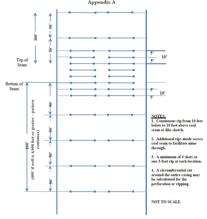
(3) When cleaning out the well as provided for in subparagraph (a)(1), the operator shall make a diligent effort to remove all of the casing in the well. After the well is completely cleaned out and all the casing removed, the well should be plugged to the total depth by pumping expanding cement slurry and pressurizing to at least 200 psi. If the casing cannot be removed, it must be cut, milled, perforated or ripped at all mineable coal seam levels to facilitate the removal of any remaining casing in the coal seam by the mining equipment. Any casing which remains shall be perforated or ripped to permit the injection of cement into voids within and around the well. All casing remaining at mineable coal seam levels shall be perforated or ripped at least every 5 feet from 10 feet below the coal seam to 10 feet above the coal seam, as shown in Appendix A.
Perforations or rips are required at least every 50 feet from 200 feet (400 feet if the total well depth is 4,000 feet or greater) below the base of the lowest mineable coal seam up to 100 feet above the uppermost mineable coal seam. See Appendix A. The mine operator must take appropriate steps to ensure that the annulus between the casing and the well walls are filled with expanding (minimum 0.5% expansion upon setting) cement and contain no voids.
If it is not possible to remove all of the casing, the operator shall notify the District Manager before any other work is performed. If the well cannot be cleaned out or the casing removed, the operator shall prepare the well as described from the surface to at least 200 feet below the base of the lowest mineable coal seam for wells less than 4000 feet in depth and 400 feet below the lowest mineable coal seam for wells 4000 feet or greater, unless the District Manager requires cleaning out and removal of casing to a greater depth based on his judgement as to what is required due to geological strata, or due to the pressure within the well.
If the operator, using a casing bond log can demonstrate to the satisfaction of the District Manager that all annuli in the well are already adequately sealed with cement, then the operator will not be required to perforate or rip the casing for that particular well. When multiple casing and tubing strings are present in the coal horizon(s), any casing which remains shall be ripped or perforated and filled with expanding cement as indicated above. An acceptable casing bond log for each casing and tubing string is needed if used in lieu of ripping or perforating multiple strings.
(4) If the District Manager concludes that the completely cleaned-out well is emitting excessive amounts of gas, the operator must place a mechanical bridge plug in the well. It must be placed in a competent stratum at least 200 feet (400 feet if the total well depth is 4,000 feet or greater) below the base of the lowest mineable coal seam, but above the top of the uppermost hydrocarbon-producing stratum, unless the District Manager requires a greater distance based on his judgment that it is required due to the geological strata, or due to the pressure within the well. The operator shall provide the District Manager with all information it possesses concerning the geological nature of the strata and the pressure of the well. If it is not possible to set a mechanical bridge plug, an appropriately sized packer may be used. The mine operator shall document what has been done to “kill the well” and plug the carbon producing strata.
(5) If the upper-most hydrocarbon-producing stratum is within 300 feet of the base of the lowest minable coal seam, the operator shall properly place mechanical bridge plugs as described in subparagraph (a)(4) to isolate the hydrocarbon- producing stratum from the expanding cement plug.
Nevertheless, the operator shall place a minimum of 200 feet (400 feet if the total well depth is 4,000 feet or greater) of expanding cement below the lowest mineable coal seam, unless the District Manager requires a greater distance based on his judgment that it is required due to the geological strata, or due to the pressure within the well.
b. MANDATORY PROCEDURES FOR PLUGGING OR RE-PLUGGING OIL OR GAS WELLS TO THE SURFACE
After completely cleaning out the well as specified in paragraph 2(a) above, the following procedures shall be used to plug or re-plug wells:
(1) The operator shall pump expanding cement slurry down the well to form a plug which runs from at least 200 feet (400 feet if the total well depth is 4,000 feet or greater) below the base of the lowest mineable coal seam (or lower if required by the District Manager based on his judgment that a lower depth is required due to the geological strata, or due to the pressure within the well) to the surface. The expanding cement will be placed in the well under a pressure of at least 200 pounds per square inch.
Portland cement or a lightweight cement mixture may be used to fill the area from 100 feet above the top of the uppermost mineable coal seam (or higher if required by the District Manager based on his judgment that a higher distance is required due to the geological strata, or due to the pressure within the well) to the surface.
(2) The operator shall embed steel turnings or other small magnetic particles in the top of the cement near the surface to serve as a permanent magnetic monument of the well. In the alternative, a 4-inch or larger diameter casing, set in cement, shall extend at least 36 inches above the ground level with the API well number engraved or welded on the casing. When the hole cannot be marked with a physical monument (e.g. prime farmland), high-resolution GPS coordinates (one-half meter resolution) are required.
c. MANDATORY PROCEDURES FOR PLUGGING OR RE-PLUGGING OIL AND GAS WELLS FOR USE AS DEGASIFICATION WELLS
After completely cleaning out the well as specified in paragraph 2(a) above, the following procedures shall be utilized when plugging or re-plugging wells that are to be used as degasification wells:
(1) The operator shall set a cement plug in the well by pumping an expanding cement slurry down the tubing to provide at least 200 feet (400 feet if the total well depth is 4,000 feet or greater) of expanding cement below the lowest mineable coal seam, unless the District Manager requires a greater depth based on his judgment that a greater depth is required due to the geological strata, or due to the pressure within the well. The expanding cement will be placed in the well under a pressure of at least 200 pounds per square inch. The top of the expanding cement shall extend at least 50 feet above the top of the coal seam being mined, unless the District Manager requires a greater distance based on his judgment that a greater distance is required due to the geological strata, or due to the pressure within the well.
(2) The operator shall securely grout into the bedrock of the upper portion of the degasification well a suitable casing in order to protect it. The remainder of this well may be cased or uncased.
(3) The operator shall fit the top of the degasification casing with a wellhead equipped as required by the District Manager in the approved ventilation plan. Such equipment may include check valves, shut-in valves, sampling ports, flame arrestor equipment, and security fencing.
(4) Operation of the degasification well shall be addressed in the approved ventilation plan. This may include periodic tests of methane levels and limits on the minimum methane concentrations that may be extracted.
(5) After the area of the coal mine that is degassed by a well is sealed or the coal mine is abandoned, the operator must plug all degasification wells using the following procedures:
(i) The operator shall insert a tube to the bottom of the well or, if not possible, to within 100 feet above the coal seam being mined. Any blockage must be removed to ensure that the tube can be inserted to this depth.
(ii) The operator shall set a cement plug in the well by pumping Portland cement or a lightweight cement mixture down the tubing until the well is filled to the surface.
(iii) The operator shall embed steel turnings or other small magnetic particles in the top of the cement near the surface to serve as a permanent magnetic monument of the well. In the alternative, a 4-inch or larger casing, set in cement, shall extend at least 36 inches above the ground level with the API well number engraved or welded on the casing.
d. MANDATORY ALTERNATIVE PROCEDURES FOR PREPARING AND PLUGGING OR RE-PLUGGING OIL OR GAS WELLS
The following provisions apply to all wells which the operator determines, and with which the MSHA District Manager agrees, cannot be completely cleaned out due to damage to the well caused by subsidence, caving, or other factors.
(1) The operator shall drill a hole adjacent and parallel to the well, to a depth of at least 200 feet (400 feet if the total well depth is 4,000 feet or greater) below the lowest mineable coal seam, unless the District Manager requires a greater depth based on his judgment that a greater depth is required due to the geological strata, or due to the pressure within the well.
(2) The operator shall use a geophysical sensing device to locate any casing which may remain in the well.
(3) If the well contains casing(s), the operator shall drill into the well from the parallel hole. From 10 feet below the coal seam to 10 feet above the coal seam, the operator shall perforate or rip all casings at least every 5 feet. Beyond this distance, the operator shall perforate or rip at least every 50 feet from at least 200 feet (400 feet if the total well depth is 4,000 feet or greater) below the base of the lowest mineable coal seam up to 100 feet above the seam being mined, unless the District Manager requires a greater distance based on his judgment that a greater distance is required due to the geological strata, or due to the pressure within the well. The diagram shown in Appendix A is representative of the locations of the perforations or ripping that must be done. The operator shall fill the annulus between the casings and between the casings and the well wall with expanding (minimum 0.5% expansion upon setting) cement, and shall ensure that these areas contain no voids. If the operator, using a casing bond log, can demonstrate to the satisfaction of the
District Manager that the annulus of the well is adequately sealed with cement, then the operator will not be required to perforate or rip the casing for that particular well, or fill these areas with cement. When multiple casing and tubing strings are present in the coal horizon(s), any casing which remains shall be ripped or perforated and filled with expanding cement as indicated above. An acceptable casing bond log for each casing and tubing string is needed if used in lieu of ripping or perforating multiple strings.
(4) Where the operator determines, and the District Manager agrees, that there is insufficient casing in the well to allow the method outlined in subparagraph (d)(3) to be used, then the operator shall use a horizontal hydraulic fracturing technique to intercept the original well. From at least 200 feet (400 feet if the total well depth is 4,000 feet or greater) below the base of the lowest mineable coal seam to a point at least 50 feet above the seam being mined, the operator shall fracture in at least six places at intervals to be agreed upon by the operator and the District Manager after considering the geological strata and the pressure within the well. The operator shall then pump expanding cement into the fractured well in sufficient quantities and in a manner which fills all intercepted voids.
(5) The operator shall prepare down-hole logs for each well. Logs shall consist of a caliper survey, a gamma log, a bond log and a deviation survey for determining the top, bottom, and thickness of all coal seams down to the lowest minable coal seam, potential hydrocarbon producing strata and the location of any existing bridge plug. The operator may obtain the logs from the adjacent hole rather than the well if the condition of the well makes it impractical to insert the equipment necessary to obtain the log.
(6) A journal shall be maintained describing the depth of each material encountered; the nature of each material encountered; bit size and type used to drill each portion of the hole; length and type of each material used to plug the well; length of casing(s) removed, perforated or ripped or left in place; any sections where casing was cut or milled; and other pertinent information concerning sealing the well. Invoices, work-orders, and other records relating to all work on the well shall be maintained as part of this journal and provided to MSHA upon request.
(7) After the operator has plugged the well as described in subparagraphs (d)(3) and/or (d)(4), the operator shall plug the adjacent hole, from the bottom to the surface, with Portland cement or a lightweight cement mixture. The operator shall embed steel turnings or other small magnetic particles in the top of the cement near the surface to serve as a permanent magnetic monument of the well. In the alternative, a 4-inch or larger casing, set in cement, shall extend at least 36 inches above the ground level.
A combination of the methods outlined in subparagraphs (d)(3) and (d)(4) may have to be used in a single well, depending upon the conditions of the hole and the presence of casings. The operator and the District Manager shall discuss the nature of each hole.
The District Manager may require that more than one method be utilized. The mine operator may submit an alternative plan to the District Manager for approval to use different methods to address wells that cannot be completely cleaned out. The District Manager may require additional documentation and certification by a registered petroleum engineer to support the proposed alternative methods.
3. MANDATORY PROCEDURES FOR PREPARING, PLUGGING, AND REPLUGGING SDD WELLS
a. MANDATORY COMPUTATIONS AND ADMINISTRATIVE PROCEDURES PRIOR TO PLUGGING OR REPLUGGING
1. Probable Error of Location – Directional drilling systems rely on sophisticated angular measurement systems and computer models to calculate the estimated location of the well bore. This estimated hole location is subject to cumulative measurement errors so that the distance between actual and estimated location of the well bore increases with the depth of the hole. Modern directional drilling systems are typically accurate within one or two degrees depending on the specific equipment and techniques.
The probable error of location is defined by a cone described by the average accuracy of angular measurement around the length of the hole. For example: a hole that is drilled 500 vertical feet and deviated into a coal seam at a depth of 700 feet would have a probable error of location at a point that is 4,000 feet from the hole collar (about 2,986 ft. horizontally from the well collar) of 69.8 ft. (4,000 ft. x sine (1.0 degree)) if the average accuracy of angular measurement was one degree and 139.6 ft. if the average accuracy of angular measurement was two degrees. In addition to the probable error of location, the true hole location is also affected by underground survey errors, surface survey errors, and random survey errors.
2. Minimum Working Barrier Around Well – For purposes of this Order, the minimum working barrier around any coalbed methane well or branches of a coalbed methane well in the coal seam is 50 feet plus the probable error of location. For example: for a hole that is drilled 500 vertical feet and deviated into a coal seam at a depth of 700 feet using drilling equipment that has an average accuracy of angular measurement of one degree, the probable error of location at a point that is 4,000 feet from the hole collar is 69.8 ft. Therefore, the minimum working barrier around this point of the well bore is 120 ft. (69.8 ft. plus 50 ft., rounded up to the nearest foot). The 50 additional feet is a reasonable separation between the probable location of the well and mining operations. When mining is within the minimum working barrier distance from a coalbed methane well or branch, the mine operator must comply with the provisions of this Order. Coalbed methane wells must be prepared in advance for safe intersection and specific procedures must be followed on the mining section in order to protect the miners when mining within this minimum working barrier around the well.
The District Manager may require a greater minimum working barrier around coalbed methane wells where geologic conditions, historical location errors, or other factors warrant a greater barrier.
3. Ventilation Plan Requirements – The ventilation plan shall contain a description of all SDD coalbed methane wells drilled in the area to be mined. This description should include the well numbers, the date drilled, the diameter, the casing information, the coal seams developed, maximum depth of the wells, abandonment pressures, and any other information required by the District Manager. All or part of this information may be listed on the 30C.F.R. § 75.372 map.
The ventilation plan shall include the techniques that the mine operator plans to use to prepare the SDD wells for safe intersection, the specifications and steps necessary to implement these techniques, and the required operational precautions that are required when mining within the minimum working barrier. In addition, the ventilation plan will contain any additional information or provisions related to the SDD wells required by the District Manager.
4. Ventilation Map – The ventilation map specified in 30 C.F.R. § 75.372 shall contain the following information:
i. The surface location of all coalbed methane wells in the active mining area and any projected mining area as specified in 30 C.F.R.§ 75.372(b)(14);
ii. Identifying information of coalbed methane wells (i.e. API hole number or equivalent);
iii. The date that gas production began from the well;
iv. The coal seam intersection of all coalbed methane wells;
v. The horizontal extents in the coal seam of all coalbed methane wells and branches;
vi. The outline of the probable error of location of all coalbed methane wells; and
vii. The date of mine intersection and the distance between estimated and actual locations for all intersections of the coalbed methane well and branches.
b. MANDATORY PROCEDURES FOR PLUGGING OR REPLUGGING SDD WELLS
The mine operator shall include one or more of the following methods to prepare SDD wells for safe intersection in the mine ventilation plan. The methods approved in the ventilation plan must be completed on each SDD well before mining encroaches on the minimum working barrier around the well or branch of the well in the coal seam being mined.
If methane leakage through subsidence cracks is a problem when retreat mining, the minimum working barrier must be maintained around wells and branches in overlying coal seams or the wells and branches must be prepared for safe intersection as specified in the mine ventilation plan.
1. Cement Plug – Cement may be used to fill the entire SDD hole system. Squeeze cementing techniques are necessary for SDD plugging due to the lack of tubing in the hole. Cement should fill void spaces and eliminate methane leakage along the hole. Once the cement has cured, the SDD system may be intersected multiple times without further hole preparation. Gas cutting occurs if the placement pressure of the cement is less than the methane pressure in the coal seam. Under these conditions, gas will bubble out of the coal seam and into the unset cement creating a pressurized void or series of interconnected pressurized voids. Water cutting occurs when formation water and standing water in the hole invades or displaces the unset cement. Standing water has to be bailed out of the hole or driven into the formation with compressed gas to minimize water cutting. The cement pressure must be maintained higher than the formation pressure until the cement sets to minimize both gas and water cutting. The cementing program in the ventilation plan must address both gas and water cutting.
Due to the large volume to be cemented and potential problems with cement setting prior to filling the entire SDD system, adequately sized pumping units with back-up capacity must be used. Various additives such as retarders, lightweight extenders, viscosity modifiers, thixotropic modifiers, and fly ash may be used in the cement mix. The volume of cement pumped should exceed the estimated hole volume to ensure the complete filling of all voids. The complete cementing program, including hole dewatering, cement, additives, pressures, pumping times and equipment must be specified in the ventilation plan.
The material safety data sheets (MSDS) for all cements, additives and components and any personal protective equipment and techniques to protect workers from the potentially harmful effects of the cement and cement components should be included in the ventilation plan. Records of cement mixes, cement quantities, pump pressures, and flow rates and times should be retained for each hole plugged.
SDD holes may be plugged with cement years in advance of mining. However, the District Manager shall require suitable documentation of the cement plugging in order to approve mining within the minimum working barrier around coalbed methane wells.
2. Polymer Gel - Polymer gels start out as low viscosity, water-based mixtures of organic polymers that are cross-linked using time-delayed activators to form a water-insoluble, high-viscosity gel after being pumped into the SDD system. Although polymer gel systems never solidify, the activated gel should develop sufficient strength to resist gas flow. A gel that is suitable for treating SDD wells for mine intersection will reliably fill the SDD system and prevent gas-filled voids. Any gel chemistry used for plugging SDD wells should be resistant to bacterial and chemical degradation and remain stable for the duration of mining through a SDD system.
Water may dilute the gel mixture to the point where it will not set to the required strength. Water in the holes should be removed before injecting the gel mixture. Water removal can be accomplished by conventional bailing and then injecting compressed gas to squeeze the water that accumulates in low spots back into the formation. Gas pressurization should be continued until the hole is dry. Another potential problem with gels is that dissolved salts in the formation waters may interfere with the cross-linking reactions. Any proposed gel mixtures must be tested with actual formation waters.
Equipment to mix and pump gels should have adequate capacity to fill the hole before the gel sets. Back-up units should be available in case something breaks while pumping. The volume of gel pumped should exceed the estimated hole volume to ensure the complete filling of all voids and allow for gel to infiltrate the joints in the coal seam surrounding the hole. Gel injection and setting pressures should be specified in the ventilation plan.
To reduce the potential for an inundation of gel, the final level of gel should be close to the level of the coal seam and the remainder of the hole
should remain open to the atmosphere until mining in the vicinity of the SDD system is completed. Packers may be used to isolate portions of the SDD system.
The complete polymer gel program, including advance testing of the gel with formation water, dewatering systems, gel specifications, gel quantities, gel placement, pressures, and pumping equipment must be specified in the ventilation plan. The MSDS for all gel components and any personal protective equipment and techniques to protect workers from the potentially harmful effects of the gel and gel components should be included in the ventilation plan. A record of the calculated hole volume, gel quantities, gel formulation, pump pressures, and flow rates and times should be retained for each hole that is treated with gel. Other gel chemistries other than organic polymers may be included in the ventilation plan with appropriate methods, parameters, and safety precautions.
3. Bentonite Gel – High-pressure injection of bentonite gel into the SDD system will infiltrate the cleat and butt joints of the coal seam near the well bore and effectively seal these conduits against the flow of methane. Bentonite gel is a thixotropic fluid that sets when it stops moving. Bentonite gel has a significantly lower setting viscosity than polymer gel. While the polymer gel fills and seals the borehole, the lower strength bentonite gel must penetrate the fractures and jointing in the coal seam in order to be effective in reducing formation permeability around the hole. The use of bentonite gel is restricted to depleted CBM applications that have low abandonment pressures and limited recharge potential. In general, these applications will be mature CBM fields with long production histories.
A slug of water should be injected prior to the bentonite gel in order to minimize moisture-loss bridging near the well bore. The volume of gel pumped should exceed the estimated hole volume to ensure that the gel infiltrates the joints in the coal seam for several feet surrounding the hole. Due to the large gel volume and potential problems with premature thixotropic setting, adequately sized pumping units with back-up capacity are required.
Additives to the gel may be required to modify viscosity, reduce filtrates, reduce surface tension, and promote sealing of the cracks and joints around the hole. To reduce the potential for an inundation of bentonite gel, the final level of gel should be approximately the elevation of the coal seam and the remainder of the hole should remain open to the atmosphere until mining in the vicinity of the SDD system is completed. If a water
column is used to pressurize the gel, it must be bailed down to the coal seam elevation prior to intersection.
The complete bentonite gel program, including formation infiltration and permeability reduction data, hole pretreatment, gel specifications, additives, gel quantities flow rates, injection pressures and infiltration times, must be specified in the ventilation plan. The ventilation plan should list the equipment used to prepare and pump the gel. The MSDS for all gel components and any personal protective equipment and techniques to protect workers from the potentially harmful effects of the gel and additives should be included in the ventilation plan. A record of hole preparation, gel quantities, gel formulation, pump pressures, and flow rates and times should be retained for each hole that is treated with bentonite gel.
4. Active Pressure Management and Water Infusion - Reducing the pressure in the hole to less than atmospheric pressure by operating a vacuum blower connected to the wellhead may facilitate safe intersection of the hole by a coal mine. The negative pressure in the hole will limit the quantity of methane released into the higher pressure mine atmosphere. If the mine intersection is near the end of a horizontal branch of the SDD system, air will flow from the mine into the upstream side of the hole and be exhausted through the blower on the surface. On the downstream side of the intersection, if the open hole length is short, the methane emitted from this side of the hole may be diluted to safe levels with ventilation air. Conversely, safely intersecting this system near the bottom of the vertical hole may not be possible because the methane emissions from the multiple downstream branches may be too great to dilute with ventilation air. The methane emission rate is directly proportional to the length of the open hole. Successful application of vacuum systems may be limited by caving of the hole or water collected in dips in the SDD system.
Another important factor in the success of vacuum systems is the methane liberation rate of the coal formation around the well—older, more depleted wells that have lower methane emission rates are more amenable to this technique. The remaining methane content and the formation permeability should be addressed in the ventilation plan.
Packers may be used to reduce methane inflow into the coal mine after intersection. All packers on the downstream side of the hole must be equipped with a center pipe so that the inby methane pressure may be measured or so that water may be injected. Subsequent intersections should not take place if pressure in a packer-sealed hole is excessive.
Alternatively, methane produced by the downstream hole may be piped to an in-mine degas system to safely transport the methane out of the mine or may be piped to the return air course for dilution. In-mine methane piping should be protected as stipulated in “Piping Methane in Underground Coal Mines,” MSHA IR 1094, (1978). Protected methane diffusion zones may be established in return air courses if needed.
Detailed sketches and safety precautions for methane collection, piping and diffusion systems must be included in the ventilation plan (30 C.F.R.
§ 75.371(ee)).
Water infusion prior to intersecting the well will temporarily limit methane flow. Water infusion may also help control coal dust levels during mining. High water infusion pressures may be obtained prior to the initial intersection by the hydraulic head resulting from the hole depth or by pumping. Water infusion pressures for subsequent intersections are limited by leakage around in-mine packers and limitations of the mine water distribution system. If water is infused prior to the initial intersection, the water level in the hole shall not be more than 100 feet before the intersection.
The complete pressure management strategy including negative pressure application, wellhead equipment, and use of packers, in-mine piping, methane dilution, and water infusion must be specified in the ventilation plan. Procedures for controlling methane in the downstream hole must be specified in the ventilation plan. The remaining methane content and formation permeability should be addressed in the ventilation plan. The potential for the coal seam to cave into the well should be addressed in the ventilation plan. Dewatering methods should be included in the ventilation plan.
A record of the negative pressures applied to the system, methane liberation, use of packers and any water infusion pressures and application time should be retained for each intersection.
19
Remedial work – If problems are encountered in preparing the holes for safe intersection, then remedial measures must be taken to protect the miners. For example: if only one-half of the calculated hole volume of cement could be placed into a SDD well due to hole blockage, holes should be drilled near each branch that will be intersected and squeeze cement using pressures sufficient to fracture into the potentially empty SDD holes. The District Manager will approve remedial work in the ventilation plan on a case-by-case basis.
4. MANDATORY PROCEDURES AFTER APPROVAL HAS BEEN GRANTED BY THE DISTRICT MANAGER TO MINE WITHIN A 100-FOOT DIAMETER BARRIER AROUND WELL OR WITHIN THE MINIMUM WORKING BARRIER AROUND THE SDD WELL OR BRANCH OF THE SDD WELL
a. A representative of the operator, a representative of the miners, the appropriate State agency, or the MSHA District Manager may request that a conference be conducted prior to intersecting any plugged or re-plugged well. Upon receipt of any such request, the District Manager shall schedule such a conference. The party requesting the conference shall notify all other parties listed above within a reasonable time prior to the conference to provide opportunity for participation. The purpose of the conference shall be to review, evaluate, and accommodate any abnormal or unusual circumstance related to the condition of the well or surrounding strata when such conditions are encountered.
b. The operator shall intersect a well on a shift approved by the District Manager. The operator shall notify the District Manager and the miners’ representative in sufficient time prior to intersecting a well in order to provide an opportunity to have representatives present.
c. When using continuous mining methods, the operator shall install drivage sights at the last open crosscut near the place to be mined to ensure intersection of the well. The drivage sites shall not be more than 50 feet from the well. When using longwall mining methods, distance markers shall be installed on
5-foot centers for a distance of 50 feet in advance of the well or branch in the headgate entry and in the tailgate entry.
d. The operator shall ensure that fire-fighting equipment including fire extinguishers, rock dust, and sufficient fire hose to reach the working face area of the well or branch intersection (when either the conventional or continuous mining method is used) is available and operable during all well or branch intersections. The fire hose shall be located in the last open crosscut of the entry or room. The operator shall maintain the water line to the belt conveyor tailpiece along with a sufficient amount of fire hose to reach the farthest point of penetration on the section. When the longwall mining method is used, a hose to the longwall water supply is sufficient.
e. The operator shall ensure that sufficient supplies of roof support and ventilation materials shall be available and located at the last open crosscut. In addition, emergency plugs and suitable sealing materials shall be available in the immediate area of the well or branch intersection.
f. On the shift prior to intersecting the well or branch, the operator shall service all equipment and check it for permissibility. Water sprays, water pressures, and water flow rates used for dust and spark suppression shall be examined and any deficiencies corrected.
g. The operator shall calibrate the methane monitor(s) on the longwall, continuous mining machine, or cutting machine and loading machine on the shift prior to intersecting the well or branch.
h. When mining is in progress, the operator shall perform tests for methane with a handheld methane detector at least every 10 minutes from the time that mining with the continuous mining machine or longwall face is within 30 feet of the well or branch until the well or branch is intersected. During the actual cutting process, no individual shall be allowed on the return side until the well or branch intersection has been completed, and the area has been examined and declared safe. All workplace examinations on the return side of the shearer will be conducted while the shearer is idle. The operator’s most current Approved Ventilation Plan will be followed at all times unless the District Manager deems a greater air velocity for the intersect is necessary.
i. When using continuous or conventional mining methods, the working place shall be free from accumulations of coal dust and coal spillages, and rock dust shall be placed on the roof, rib, and floor to within 20 feet of the face when intersecting the well or branch. On longwall sections, rock dusting shall be conducted and placed on the roof, rib, and floor up to both the headgate and tailgate gob.
j. When the well or branch is intersected, the operator shall de-energize all equipment, and thoroughly examine and determine the area to be safe before permitting mining to resume.
k. After a well or branch has been intersected and the working place determined to be safe, mining shall continue inby the well or branch a sufficient distance to permit adequate ventilation around the area of the well or branch. A packer will be installed in any open or unplugged portion of the hole as soon as it is safe to do so.
l. If the casing is cut or milled at the coal seam level, the use of torches should not be necessary. However, in rare instances, torches may be used for inadequately or inaccurately cut or milled casings. No open flame shall be permitted in the area until adequate ventilation has been established around the well or branch bore and methane levels of less than 1.0% are present in all areas that will be exposed to flames and sparks from the torch. The operator shall apply a thick layer of rock dust to the roof, face, floor, ribs and any exposed coal within 20 feet of the casing prior to the use of torches.
m. Non-sparking (brass) tools will be located on the working section and will be used exclusively to expose and examine cased well or branches.
n. No person shall be permitted in the area of the well or branch intersection except those actually engaged in the operation, including company personnel, representatives of the miners, personnel from MSHA, and personnel from the appropriate State agency.
o. The operator shall alert all personnel in the mine to the planned intersection of the well or branch prior to their going underground if the planned intersection is to occur during their shift. This warning shall be repeated for all shifts until the well or branch has been mined through.
p. The well or branch intersection shall be under the direct supervision of a certified individual. Instructions concerning the well or branch intersection shall be issued only by the certified individual in charge.
q. If the mine operator cannot find the well or branch in the middle of the panel or a gate section misses the anticipated intersection, mining shall cease and the District Manager shall be notified.
r. The provisions of this Order do not impair the authority of representatives of MSHA to interrupt or halt the well or branch intersection, and to issue a withdrawal order, when they deem it necessary for the safety of the miners. MSHA may order an interruption or cessation of the well or branch intersection and/or a withdrawal of personnel by issuing either a verbal or written order to that effect to a representative of the operator, which order shall include the basis for the order. Operations in the affected area of the mine may not resume until a representative of MSHA permits resumption. The mine operator and miners shall comply with verbal or written MSHA orders immediately. All verbal orders shall be committed to writing within a reasonable time as conditions permit.
s. A copy of this Order shall be maintained at the mine and be available to the miners.
t. If the well or branch is not plugged to the total depth of all minable coal seams identified in the core hole logs, any coal seams beneath the lowest plug will remain subject to the barrier requirements of 30 C.F.R. § 75.1700, should those coal seams be developed in the future.
u. All necessary safety precautions and safe practices according to Industry Standards, required by MSHA regulations and State regulatory agencies having jurisdiction over the plugging site will be followed to provide the utmost protection to the miners involved in the process.
v. All miners involved in the plugging or re-plugging operations will be trained on the contents of this petition prior to starting the process and a copy of this petition will be posted at the well or branch site until the plugging or re- plugging has been completed.
w. Mechanical bridge plugs should incorporate the best available technologies that are either required or recognized by the State regulatory agency and/or oil and gas industry.
x. Within 30 days after this Order becomes final, the operator shall submit proposed revisions for it’s approved 30 C.F.R. Part 48 training plan to the District Manager. These proposed revisions shall include initial and refresher training on compliance with the terms and conditions stated in the Order. The operator shall provide all miners involved in well or branch intersection with training on the requirements of this Order prior to mining within 150 feet of the next well or branch intended to be mined through.
y. The responsible person required under 30 C.F.R. § 75.1501 Emergency Evacuations, is responsible for well or branch intersection emergencies. The well or branch intersection procedures should be reviewed by the responsible person prior to any planned intersection.
z. Within 30 days after this Order becomes final, the operator shall submit proposed revisions for its approved mine emergency evacuation and firefighting program of instruction required under 30 C.F.R § 75.1502. The operator will revise the program of instruction to include the hazards and evacuation procedures to be used for well or branch intersections. All underground miners will be trained in this revised plan within 30 days of submittal.
5. MANDATORY PROCEDURES SPECIFIC TO SDD INTERSECTIONS
a. Following the initial intersection of a branch of an SDD well, subsequent intersections of the same branch of the SDD well typically have lower risk. Appropriate procedures to protect the miners prior to these subsequent intersections or a given branch shall be specified in the ventilation plan.
b. All intersections with SDD wells and branches that are in intake air courses shall be examined as part of the pre-shift examinations required under 30C.F.R. § 75.360.
c. All other intersection with SDD wells and branches shall be examined as part of the weekly examinations required under 30 C.F.R. § 75.364.
Any party to this action desiring a hearing on this matter must file in accordance with 30 C.F.R. § 44.14, within 30 days. The request for hearing must be filed with the Administrator for Mine Safety and Health Enforcement, 201 12th Street South, Suite 401, Arlington, Virginia 22202-5452.
If a hearing is requested, the request shall contain a concise summary of position on the issues of fact or law desired to be raised by the party requesting the hearing, including specific objections to the proposed decision.
A party other than Petitioner who has requested a hearing shall also comment upon all issues of fact or law presented in the petition, and any party to this action requesting a hearing may indicate a desired hearing site. If no request for a hearing is filed within 30 days after service thereof, the Decision and Order will become final and must be posted by the operator on the mine bulletin board at the mine.
Timothy R. Watkins
Administrator for
Mine Safety and Health Enforcement
Certificate of Service
I hereby certify that a copy of this proposed decision was served personally or mailed,
postage prepaid, or provided by other electronic means this 30th day of April 2021, to:
Ryan Toler General Manager
Century Mining LLC –
Longview Mine
200 Chapel Brook Drive
Bridgeport, WV 26330
Don Vickers
Safety and Health Specialist
cc: Eugene White, Director Office of Miners' Health Safety & Training #7 Players Club Dr. Suite 2, Charleston WV 25311 Eugene.E.White@wv.gov