2/23/2024
In the matter of Petition for Modification
Marion County Coal Resources, Inc.
Marion County Mine
I.D. No. 46-01433 Docket No. M-2023-003-C
PROPOSED DECISION AND ORDER
On February 13, 2023, Marion County Coal Resources, Inc., filed an Amended Petition for Modification for the Marion County Mine. The Petition requests modification of standard 30 C.F.R. § 75.1700 as it pertains to an alternative method of compliance with respect to unconventional gas wells within the Marcellus shale.
The Petitioner alleges that the proposed alternative method will, at all times, guarantee no less than the same measure of protection afforded miners under 30 C.F.R. § 75.1700 as that provided by the standard, which states:
§ 75.1700 Oil and gas wells.
Each operator of a coal mine shall take reasonable measures to locate oil and gas wells penetrating coalbeds or any underground area of a coal mine. When located, such operator shall establish and maintain barriers around such oil and gas wells in accordance with State laws and regulations, except that such barriers shall not be less than 300 feet in diameter, unless the Secretary or his authorized representative permits a lesser barrier consistent with the applicable State laws and regulations where such lesser barrier will be adequate to protect against hazards from such wells to the miners in such mine, or unless the Secretary or his authorized representative requires a greater barrier where the depth of the mine, other geologic conditions, or other factors warrant such a greater barrier.
BACKGROUND
Marion County Mine is located in Marion County, West Virginia. The mine is a belt haulage coal mine, mining the Pittsburgh #8 coal seam with average depth of cover of approximately 850 to 1000 feet. The mine has eight air shafts and one slope opening located at Sugar Run Portal in Fairview, West Virginia. The mine operates one
continuous mining machine section and a longwall section to produce coal. Conveyor belts transport the coal from the working sections to the preparation plant located near the slope. The mine currently operates with 519 employees. The mine operates five days a week with three production shifts. The average daily production at the mine is approximately 25,000 raw tons of coal per day. The mine liberates up to 9,000,000 cubic feet of methane on a daily basis.
The miners are represented by the United Mine Workers of America (UMWA). Questions and comments were solicited from the miners and a copy of the petition was posted on the bulletin board at the mine site.
Information was collected during the investigation specific to the petitioner’s request to plug and mine through the Jones 2H and 3H gas wells as follows:
1. The J o n e s 2 H Marcellus Gas well API#: 47-049-02184. The Petitioner submitted Exhibit D as supplementary information providing details for the Jones 2H gas well such as casing diameters, depths, tops of cement, pressures, production history, site specific geology, locations of gas producing formations, relevant logging information, well plat of surface location, mine map with gas well location, well record and completion report. Exhibit D is referenced in this Proposed Decision and Order (PDO), however it will not be attached due to the large volume of material provided.
2. The Jones 3H Marcellus Gas well API#: 47-049- 02283. The Petitioner submitted Exhibit F as supplementary information providing details for the Jones 3H gas well such as casing diameters, depths, tops of cement, pressures, production history, site specific geology, locations of gas producing formations, relevant logging information, well plat of surface location, mine map with gas well location, well record and completion report. Exhibit F is referenced in this Proposed Decision and Order (PDO), however it will not be attached due to the large volume of material provided.
MSHA investigators conducted an investigation into the merits of the petition and filed a written report of their findings with the Administrator for Mine Safety and Health Enforcement. After a careful review of the entire record, including the petition and MSHA's investigative report, the Administrator issues this Proposed Decision and Order.
FINDINGS OF FACT AND CONCLUSIONS OF LAW
The Morgantown District conducted their investigation of the petition for modification between April 24, 2023 and May 8, 2023, which included review of this petition by
Technical Support personnel. The miners at the Marion County Mine are represented by a labor union; and a miner’s representative participated in the investigation.
Plugging and mining through unconventional wells presents higher risk to the miners than low pressure, low volume conventional wells. Therefore the procedures followed for unconventional wells must be based on the specific characteristics of the particular unconventional well to be plugged, including:
• Well construction, including all casing diameters, their depths, and tops of cement,
• Well pressure and production history,
• Site-specific geology, including the location of all potential gas-producing formations,
• Cement bond logs, well deviation logs, and other relevant logs, and
• Well plat of surface location, mine map with deviated gas well location at coal seam elevation, well record and completion report.
MSHA determined that the Petitioner has provided all the contents required by the provision. All supporting documentation including a detailed statement of the facts the Petitioner would show to establish the grounds upon which it is claimed a modification is warranted was provided.
The investigation confirmed that two “unconventional wells” (Esther Clark 1 H Marcellus Gas well API#: 4 7-061- 01616 and Esther Clark 3H Marcellus Gas well API#: 47- 061-01623 were mined through by the 3 West Longwall on November 2 & 3rd, 2022 per the Docket No. M-2021-026-C. Records of these cut through operations were provided to MSHA on November 3, 2022 with no issues or problems identified.
Coastal Drilling East LLC. also identified they had previously plugged unconventional wells for the Bailey Mine and no issues were encountered during plugging or mining by or through these wells.
Therefore, the terms and conditions as amended by MSHA will, at all times, guarantee no less than the same measure of protection afforded the miners under 30 C.F.R. § 75.1700 for plugging and mining through the identified Jones 2H and 3H Marcellus Gas wells. On the basis of the petition, comments received, and the findings of MSHA's investigation, Marion County Coal Resources, Inc. is granted a modification of the application of 30 C.F.R. § 75.1700 to its Marion County Mine.
ORDER
Wherefore, pursuant to the authority delegated by the Secretary of Labor to the Administrator for Mine Safety and Health Enforcement, and pursuant to § 101(c) of the Federal Mine Safety and Health Act of 1977, 30 U.S.C. § 811(c), it is ordered that Marion
County Coal Resources’ Petition for Modification of the application of 30 C.F.R. § 75.1700 in the Marion County Mine is hereby:
GRANTED, subject to the following terms and conditions;
1. DISTRICT MANAGER APPROVAL REQUIRED
a. This Petition specifically applies to the Jones 2H and 3H Marcellus Gas wells.
b. A safety barrier of 300 feet in diameter shall be maintained around these two gas wells until approval to proceed with mining has been obtained from the District Manager.
c. Prior to mining within the safety barrier around these wells, the mine operator shall provide to the District Manager a sworn affidavit or declaration executed by a company official, the person at the mine who is in charge of health and safety at the mine, stating that all mandatory procedures for cleaning out, preparing, and plugging each gas well has been completed as described by the terms and conditions of this petition.
The affidavit or declaration must be accompanied by all logs, electronic or otherwise, described in subparagraphs 2(a)(3) below and any other records described in those subparagraphs which the District Manager may request. The District Manager will review the affidavit or declaration, the logs and any other records that have been requested, and may inspect the well itself, and will then determine if the operator has complied with the procedures for cleaning out, preparing, and plugging each well as described by the terms and conditions of this Petition. If the District Manager determines that the procedures have been complied with, approval will be provided, and the mine operator may then mine within the safety barrier of the well, subject to the terms of this Petition.
d. The terms and conditions of this petition apply to all types of underground coal mining.
2. MANDATORY PROCEDURES FOR CLEANING OUT, PREPARING, PLUGGING THE JONES 2H AND 3H GAS WELLS
a. MANDATORY PROCEDURES FOR CLEANING OUT AND PREPARING THE JONES 2H AND 3H WELLS PRIOR TO PLUGGING
The mine operator shall test for gas emissions inside the hole before cleaning out, preparing, and plugging gas wells. The District Manager shall be
contacted if gas is being produced.
(1) Since these wells are unconventional and greater than 4,000' in depth, a diligent effort shall be made to remove all the casing in the well and clean the well down to the original arrowset packer installed just above the transition point from vertical to horizontal or "kick off point" in the well. The operator shall completely clean out the well from the surface to at least the same arrowset packer originally installed (Reference Exhibits D and F). The operator shall provide the District Manager with all information it possesses concerning the geological nature of the strata and the pressure of the well.
The operator shall make a diligent effort to remove all material from the entire diameter of the well, wall to wall. Additional details and procedures specific to cleaning out and preparing the Jones 2H and 3H gas wells can be found in Appendix A.
Since these wells are no longer producing and are being cleaned and prepared subject to this petition, the operator must: 1) attempt to remove all of the casing using a diligent effort, and comply with all other applicable provisions in this petition, or 2) if the casing cannot be removed from the total depth, must be filled with cement from the lowest possible depth to 400 feet below the Pittsburgh #8 coal seam, and the other applicable provisions in this petition still apply, or 3) if the casing cannot be removed it shall be perforated from 400 feet below the Pittsburgh #8 coal seam, and the annuli shall be cemented or otherwise filled, and the other applicable provisions in this Petition still apply.
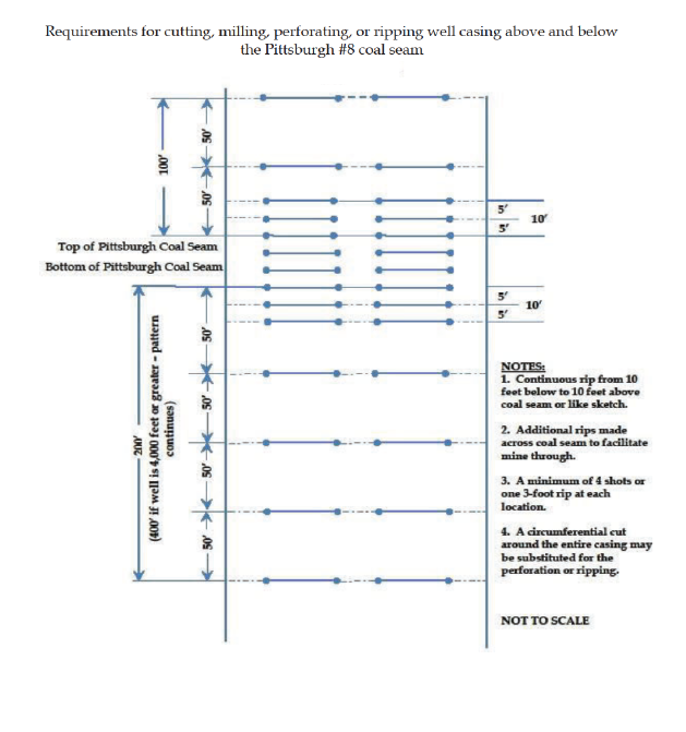
If the casing cannot be removed, it must be cut, milled, perforated or ripped at sufficient intervals to facilitate the removal of any remaining casing in the coal seam by the mining equipment. Any casing which remains shall be cut, perforated or ripped to permit the injection of cement into voids within and around the well. All casing remaining at the Pittsburgh #8 coal seam shall be cut, perforated or ripped at least every 5 feet from 10 feet below the coal seam to 10 feet above the coal seam.
In order to make a diligent effort to remove the casing, the operator shall pull a minimum of 150% of casing string weight and/or have made at least three attempts to spear or overshot to grip the casing for the required minimum pull effort. The operator shall keep a record of these efforts, including casing length and weight, and make available for MSHA review. The District Manager may reserve the right to require additional measures in efforts to remove casing, as appropriate.
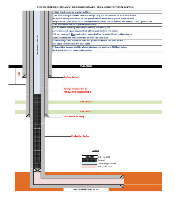
Perforations or rips are required at least every 50 feet from 400 feet below the base of the Pittsburgh #8 coal seam up to 100 feet above the uppermost mineable coal seam. For perforations in the Pittsburgh #8 seam, see Appendix B. The mine operator must take appropriate steps to ensure that the annulus between the casing and the well walls are filled with expanding (minimum 0.5% expansion upon setting) cement and contain no voids.
If it is not possible to remove all of the casing, the operator shall notify the District Manager before any other work is performed. If the well cannot be cleaned out or the casing removed, the operator shall prepare the well as described from the surface to at least 400 feet below the base of the Pittsburgh #8 coal seam, unless the District Manager requires cleaning out and removal of casing to a greater depth based on his judgement as to what is required due to geological strata, or due to the pressure within the well.
If the operator, using a casing bond log, can demonstrate to the satisfaction of the District Manager that all annuli in the well are already adequately sealed with cement, then the operator will not be required to perforate or rip the casing for that particular well. When multiple casing and tubing strings are present in the coal horizon(s), any casing which remains shall be ripped or perforated and filled with expanding cement as indicated above. An acceptable casing bond log for each casing and tubing string is needed if used in lieu of ripping or perforating multiple strings. Original bond logs for the Jones 2H and 3H gas wells can be found in Exhibits D and F which the mine operator will make available upon request.
(2) Class A cement with gas blocker is the minimum cement specification to be used as a plugging material.
(3) The operator shall prepare down-hole logs for each well. Logs shall consist of a caliper survey, a bond log if appropriate, a deviation survey, and a gamma survey for determining the top, bottom, and thickness of all coal seams down to the coal seam to be mined, or the lowest mineable coal seam, whichever is lower, potential hydrocarbon producing strata and the location of any existing bridge plug. In addition, a journal shall be maintained describing the depth of each material encountered; the nature of each material encountered; bit size and type used to drill each portion of the hole; length and type of each material used to plug the well; length of casing(s) removed, perforated or ripped or left in place; any sections where casing was cut or milled; and other pertinent information concerning cleaning and sealing the well. Invoices, work-orders, and other records relating to all work on the well shall be maintained as part of this journal and provided to MSHA upon request.
(4) A diligent effort must be made to remove the casing down to the arrowset packer installed just above the "kickoff point" (where the well transitions from vertical to horizontal (Reference Exhibits D and F). If all of the vertical casing above the existing packer can be removed, the operator shall prepare the well for plugging, and use seals described below, 400 feet below the Pittsburgh #8 coal seam. MSHA may retain the right to reviewand direct the operator's sealing protocol, in the event geologic or well conditions require further measures. Additional details and procedures specific to cleaning out, preparing, and subsequently plugging the Jones 2H and 3H Marcellus gas wells can be found in Appendix A.
(5) If the District Manager concludes that the completely cleaned-out well is emitting excessive amounts of gas, the operator must place additional mechanical bridge plugs in the well.
The mechanical bridge plug must be placed in a competent stratum at least 400 feet below the base of the lowest mineable coal seam, but above the top of the uppermost hydrocarbon-producing stratum, unless the District Manager requires a greater distance based on his judgment that it is required due to the geological strata, or due to the pressure within the well. The operator shall provide the District Manager with all information it possesses concerning the geological nature of the strata and the pressure of the well.
If it is not possible to set a mechanical bridge plug, an appropriately sized packer may be used. The mine operator shall document what has been done to "kill the well" and plug the hydrocarbon producing strata.
(6) If the upper-most hydrocarbon-producing stratum is within 300 feet of the base of the Pittsburgh #8 coal seam the operator shall properly place mechanical bridge plugs as described in subparagraph (a)(5) to isolate the hydrocarbon- producing stratum from the expanding cement plug.
Nevertheless, the operator shall place a minimum of 400 feet of expanding cement below the Pittsburgh #8 coal seam, unless the District Manager requires a greater distance based on his judgment that it is required due to the geological strata, or due to the pressure within the well.
b. MANDATORY PROCEDURES FOR PLUGGING THE JONES 2H AND 3H GAS WELLS TO THE SURFACE
After completely cleaning out the well as specified in paragraph 2(a) above, the following procedures shall be used to plug the Jones 2H and 3H wells:
(1) The operator shall pump cement slurry down the well to form a plug which
runs from at the original arrowset packer installed just above the "kick off point" in the well to 400' below the Pittsburgh #8 coal seam (see details in Appendix A and C). The cement will be placed in the well under a pressure of at least 200 pounds per square inch or as otherwise approved by the District Manager on a case-by-case basis considering the history and condition of the well. The District Manager can modify the cementing plan based on his judgment due to the geological strata or the pressure within the well.
Additional details and procedures specific to cleaning out, preparing, and subsequently plugging the Jones 2H and 3H gas wells can be found in Appendix A.
(2) The operator shall embed steel turnings or other small magnetic particles in the top of the cement near the surface to serve as a permanent magnetic monument of the well. In the alternative, a 4-inch or larger diameter casing, set in cement, shall extend at least 36 inches above the ground level with the API well number engraved or welded on the casing. When the hole cannot be marked with a physical monument (e.g. prime farmland), high- resolution GPS coordinates (one-half meter resolution) are required.
3. MANDATORY PROCEDURES WHEN MINING WITHIN A 100-FOOT DIAMETER BARRIER AROUND THE JONES 2H AND 3H GAS WELLS
a. A representative of the operator, a representative of the miners, the appropriate State agency, or the MSHA District Manager may request that a conference be conducted prior to intersecting any plugged well. Upon receipt of any such request, the District Manager shall schedule such a conference. The party requesting the conference shall notify all other parties listed above within a reasonable time prior to the conference to provide opportunity for participation. The purpose of the conference shall be to review, evaluate, and accommodate any abnormal or unusual circumstance related to the condition of the well or surrounding strata when such conditions are encountered.
b. The operator shall intersect a well on a shift approved by the District Manager. The weather will be evaluated for possible lightning
storms when deciding when to intersect the well. The operator shall notify the District Manager and the miners' representative within 48 hours prior to intersecting a well in order to provide an opportunity to have representatives present.
c. When using continuous mining methods, the operator shall install drivage sights at the last open crosscut near the place to be mined to ensure intersection of the well. The drivage sites shall not be more than 50 feet from the well. When using longwall-mining methods, distance markers shall be
installed on 5-foot centers for a distance of 50 feet in advance of the well in the headgate entry and in the tailgate entry.
d. The operator shall ensure that fire-fighting equipment including fire extinguishers, rock dust, and sufficient fire hose to reach the working face area of the well or branch intersection (when either the conventional or continuous mining method is used) is available upwind and operable during all well or branch intersections. The fire hose shall be connected, ready for use, and located in the last open crosscut of the entry or room. The operator shall maintain the water line to the belt conveyor tailpiece along with a sufficient amount of fire hose to reach the farthest point of penetration on the section. When the longwall mining method is used, a hose to the longwall water supply is sufficient, connected and ready for use.
e. The operator shall ensure that sufficient supplies of roof support and ventilation materials, emergency plugs and suitable sealing materials are placed upwind and ready for use no further outby than one crosscut from the last open crosscut of the well intersection.
f. On the shift prior to intersecting the well, the operator shall service all equipment and check it for permissibility. Water sprays, water pressures, and water flow rates used for dust and spark suppression shall be examined and any deficiencies corrected.
g. The operator shall calibrate the methane monitor(s) on the longwall, continuous mining machine, or cutting machine and loading machine on the shift prior to intersecting the well.
h. When mining is in progress, the operator shall perform tests for methane with a handheld methane detector at least every 10 minutes from the time that mining with the continuous mining machine or longwall face is within 30 feet of the well until the well is intersected. During the actual cutting process, no individual shall be allowed on the return side until the well intersection has been completed, and the area has been examined and declared safe. All workplace examinations on the return side of the shearer will be conducted while the shearer is idle. The operator's most current Approved Ventilation Plan will be followed at all times unless the District Manager deems agreater air velocity for the intersect is necessary.
i. When using continuous or conventional mining methods, the working place shall be free from accumulations of coal dust and coal spillages, and rock dust shall be placed on the roof, rib, and floor to within 20 feet of the face when
intersecting the well. On longwall sections, rock dusting shall be conducted and placed on the roof, rib, and floor up to both the headgate and tailgate gob.
j. When the well is intersected, the operator shall de- energize all equipment, and thoroughly examine and determine the area to be safe before permitting mining to resume.
k. After a well has been intersected and the working place determined to be safe, mining shall continue inby the well a sufficient distance to permit adequate ventilation around the area of the well.
l. If the casing is cut or milled at the coal seam level, the use of torches should not be necessary. However, in rare instances, torches may be used for inadequately or inaccurately cut or milled casings. No open flame shall be permitted in the area until adequate ventilation has been established around the well bore and methane levels of less than 1.0% are present in all areas that will be exposed to flames and sparks from the torch. The operator shall apply a thick layer of rock dust to the roof, face, floor, ribs and any exposed coal within 20 feet of the casing prior to the use of torches.
m. Non-sparking (brass) tools will be available and will be used exclusively to expose and examine cased wells.
n. No person shall be permitted in the area of the well intersection except those actually engaged in the operation, including company personnel, representatives of the miners, personnel from MSHA, and personnel from the appropriate State agency.
o. The operator shall alert all personnel in the mine to the planned intersection of the well prior to their going underground if the planned intersection is to occur during their shift. This warning shall be repeated for all shifts until the well has been mined through.
p. The well intersection shall be under the direct supervision of a certified individual. Instructions concerning the well intersection shall be issued only by the certified individual in charge. All miners shall be in known locations and in constant two-way communication with the responsible person under 30 C.F.R. § 75.1501 when active mining occurs within the minimum working barrier of the well or well branches.
q. If the mine operator cannot find the well in the longwall panel or if a development section misses the anticipated intersection, the operator shall cease mining to examine for hazardous conditions at the projected location of
the well, notify the District Manager, and take reasonable measures to locate the well, including visual observation/inspection or through survey data.
Mining may resume if the well is located and no hazardous conditions exist. If the well cannot be located, the mine operator shall work with the District Manager to resolve any issues before mining resumes.
r. The provisions of this Petition do not impair the authority of representatives of MSHA to interrupt or halt the well intersection, and to issue a withdrawal order, when they deem it necessary for the safety of the miners. MSHA may order an interruption or cessation of the well intersection and/or a withdrawal of personnel by issuing either a verbal or written order to that effect to a representative of the operator, which order shall include the basis for the order. Operations in the affected area of the mine may not resume until a representative of MSHA permits resumption. The mine operator and miners shall comply with verbal or written MSHA orders immediately. All verbal orders shall be committed to writing within a reasonable time as conditions permit.
s. A copy of this Petition shall be maintained at the mine and be available to the miners.
t. If the well is not plugged to the total depth of all minable coal seams identified in the core hole logs, any coal seams beneath the lowest plug will remain subject to the barrier requirements of 30 C.F.R. § 75.1700, should those coal seams be developed in the future.
u. All necessary safety precautions and safe practices according to Industry Standards, required by MSHA regulations and State regulatory agencies having jurisdiction over the plugging site will be followed to provide the upmost protection to the miners involved in the process.
v. All miners involved in the plugging or re-plugging operations will be trained on the contents of this Petition prior to starting the process and a copy of this Petition will be posted at the well site until the plugging or re-plugging has been completed.
w. Mechanical bridge plugs should incorporate the best available technologies that are either required or recognized by the State regulatory agency and/or oil and gas industry.
x. Notification. Where the operator is required to notify the District Manager pursuant to the terms of this Petition, the method of notification will be set forth
in the cut-through procedures for each well. The District Manager agrees to provide a number wherein they or their designee are available at all times.
y. Within 30 days after this Petition becomes final, the operator shall submit proposed revisions for its approved 30 C.F.R. Part 48 training plan to the District Manager. These proposed revisions shall include initial and refresher training on compliance with the terms and conditions stated in the Petition. The operator shall provide all miners involved in well intersection with training on the requirements of this Petition prior to mining within the minimum working barrier of the next well or well branch intended to be mined through.
z. The responsible person required under 30 C.F.R. § 75.1501 Emergency Evacuations, is responsible for well intersection emergencies. The well intersection procedures should be reviewed by the responsible person prior to any planned intersection. Additionally, the mine dispatcher will be notified and review procedures prior to any planned intersection.
aa. Within 30 days after this Petition becomes final, the operator shall submit proposed revisions for its approved mine emergency evacuation and firefighting program of instruction required under 30 C.F.R § 75.1502. The operator will revise the program of instruction to include the hazards and evacuation procedures to be used for well intersections. All underground miners will be trained in this revised plan within 30 days of submittal.
Any party to this action desiring a hearing on this matter must file in accordance with 30 C.F.R. § 44.14, within 30 days. The request for hearing must be filed with the Administrator for Mine Safety and Health Enforcement, 201 12th Street South, Suite 4E401, Arlington, Virginia 22202.
If a hearing is requested, the request shall contain a concise summary of position on the issues of fact or law desired to be raised by the party requesting the hearing, including specific objections to the proposed decision.
A party other than Petitioner who has requested a hearing shall also comment upon all issues of fact or law presented in the petition, and any party to this action requesting a hearing may indicate a desired hearing site. If no request for a hearing is filed within 30 days after service thereof, the Decision and Order will become final.
Brian Goepfert
Administrator for
Mine Safety and Health Enforcement
Certificate of Service
I hereby certify that a copy of this proposed decision was served personally or mailed, postage prepaid, or provided by other electronic means this 23rd day of February,2024 to:
R. Henry Moore Dave E. Dayton
Fisher & Phillips LLP UMWA Representative
6 PPG Place, Suite 830 daytonumwa@gmail.com
Pittsburgh, PA 15222
hmoore@fisherphillips.com
Timothy J. Hussion, Safety Director
Marion County Coal Resources, Inc.
151 Johnnycake Road
Metz, West Virginia 26585
timothyhussion@acnrinc.com
2/23/2024
Robert S. Roark
Mine Safety and Health Specialist
cc: McKennis Browning, Acting Director, Office of Miners' Health Safety & Training #7 Players Club Dr. Suite 2, Charleston WV 25311 McKennis.P.Browning@wv.gov
Exhibits and Appendices List
Provided by the Petitioner*
Appendix A Proposed Plugging Procedures
Appendix B Requirements for cutting, milling, perforating, or ripping well casing above and below the Pittsburgh #8 coal seam
Appendix C General Proposed Permanent Plugging Schematic for an unconventional gas well
Exhibit D Jones 2H Marcellus Gaswell Detail
Exhibit F Jones 3H Marcellus Gaswell Detail
*All Exhibit/Appendix above provided by the Petitioner are included in the PDO by reference. Appendix A, B, & C are attached below.
APPENDIX A
PROPOSED PLUGGING PROCEDURES Jones 2H API# 47-049-02184
Jones 3H API# 47-049-02283
The following detailed cleaning and plugging procedures are to comply with the additional specifics and guidelines found within the main body of the Petition for Modification part 2(a) “Mandatory Procedures for Cleaning Out and Preparing the Jones Gas Wells” and part 2(b) “Mandatory Procedures for Plugging the Jones Gas Wells to the Surface”.
1. Record the shut-in pressure and monitor the casing pressure.
2. Move in equipment. Rig up the wireline rig and the pumping unit to the well head. Load fresh water (8.3 lbs./gallon) and weighted brine water (10.0 lbs./gallon) into their respective tanks.
3. Pump sufficient amount of weighted brine water into the wellbore first. Switch to fresh water and finish loading the wellbore. Fresh and brine water will be pumped until the well is officially “killed”.
4. Rig up the wireline wellhead control. Run into the hole with a 5 1/2” – 10,000 psi rated Cast Iron Bridge Plug (CIBP) and set the CIBP within the 5 1/2” casing above the kick-off point. Pull out of the hole and rig down the wireline rig.
5. Pressure test the installed 5 1/2” – 10,000 psi CIBP up to 80% of its working pressure for a minimum of one hour (surface + hydrostatic). Record pressure test results.
6. Rig up the drill rig and install a 10,000 psi Wellhead Blowout Preventer.
7. Pressure test the Wellhead Blowout Preventer up to 90% of its working pressure for one hour. Record pressure test results.
8. Run into the hole with another 5-1/2” – 10,000 psi rated Cast Iron Bridge Plug (CIBP) and set the CIBP against the previously set 5-1/2” CIBP. Pull out of the
hole and rig down the wireline rig.Pressure test the installed 5-1/2” – 10,000 psi CIBP up to 80% of its working pressure for a minimum of one hour (surface + hydrostatic). Record the pressure test results. If it is unable to hold 80% of its working pressure, an additional CIBP will be set in the wellbore directly above it.
9. Rig up the wireline rig and perform a cement bond log to determine the “top of cement” within the annulus of the 5-1/2” casing. Preliminarily, based on the exiting well record, the 5-1/2” casing was cemented to surface. Also run gamma log to verify the bottom of 9-5/8” casing. Pull out of the hole and rig down the wireline rig.
10. Pick up the drill pipe and trip in the hole down to the installed 5-1/2” CIBP. Set a cement plug with a gas blocker additive from the existing 5- 1/2” CIBP up to the bottom of 9-5/8”. Wait on cement to cure for a minimum of eight hours.
11. Rig up the wireline rig, run into the hole to the top of the existing cement plug and cut the 5-1/2” casing below the bottom of the 9-5/8” casing (or make cut at the top of cement if bond log shows a free-point). Run out of the hole and rig down the wireline rig.
12. If the bond log shows 5-1/2” casing is free, attempt to pull 5-1/2” casing out of the hole with drill rig. Load the hole with fresh water as required.
13. Monitor the gas pressure for a minimum of one hour. Record shut-in test results. If additional gas pressure is encountered during the shut-in test, an additional CIBP or packers may be used to mitigate gas migration.
14. Skip to line 19 if the 5-1/2” casing was bonded and could not be removed.
15. Rig up the wireline rig and perform a cement bond log on the 9-5/8” casing. Pull out of the hole and rig down the wireline rig. Preliminarily, the 9-5/8” casing is expected to be fully cemented within the annulus. It was reported that cement was circulated to the surface upon install for the 5-1/2”, 9-5/8” casing, the 13-3/8” casing, and the 20” casing (see the details in the existing “Well Operator’s Report of Well Work” in Exhibits D and F). Any voids encountered within the 9-5/8” annulus will be addressed appropriately.
16. Pick up the drill pipe and trip in the hole down to the previous cement plug. Set an additional cement plug with a gas blocker additive from the existing cement plug up to 100’ above the 9-5/8” casing seat. Wait on cement to cure for a minimum of eight hours.
17. Shut-in the well and monitor the gas pressure while the cement is curing. Record shut-in test results. If additional gas pressure is encountered during the shut-in test, an additional CIBP or packers may be used to mitigate gas migration.
18. Pick up the drill pipe and trip in the hole down to the previous cement plug. Set an additional cement plug with a gas blocker additive from the existing cement plug up to 400’ below the bottom of the Pittsburgh #8 coal seam. Wait on cement to cure for a minimum of eight hours.
19. Shut-in the well and monitor the gas pressure while the cement is curing. Record shut-in test results. If additional gas pressure is encountered during the shut-in test, an additional CIBP or packers may be used to mitigate gas migration.
At this point, the well has been effectively plugged from just above the “kick-off point” (vertical to horizontal) up to 400’ below the Pittsburgh #8 coal seam. The remaining procedures to complete the plugging process from 400’ below the Pittsburgh #8 coal seam to the surface can be found in the main body of the Petition for Modification part 2(a) “Mandatory Procedures for Cleaning Out and Preparing the Jones Gas Wells”, part 2(b) “Mandatory Procedures for Plugging the Jones Gas Wells to the Surface”, and Appendix B.
Appendix B
Appendix C